Skip to Content

complexor pre-order 2026

3U 30HP Eurorack Analogue Modular Auto Compressor Limiter EQ Expander Saturator Filter

Free Worldwide Shipping for the first 70 pre-orders!

limited run of 70 modules will be produced in the first round of production, shipping by the end of 2026. Secure your module today!

This instrument is developed through careful iteration. Design, features, and specifications may change.

1,199.00 € 1,199.00 €
(Tax included)

  • choose your destiny - light side

science meets art & engineering

By incorporating established principles from compressor design research, traditional analogue low-noise methodologies, this module delivers adaptive, program-dependent dynamic range control with both technical rigor and musical relevance.

more details

playable analogue fx processor 

Its flexible topologies, customisable time constants, and robust signal path ensure its suitability for the most demanding contemporary Eurorack Modular systems. For sound producers, audio engineers and musicians alike.

learn more

complexor prototype demo video


complexor main features 

Analogue Modular Auto Compressor

Developed by ModMonk, this Analogue Modular Auto Up/Down Compressor, Limiter, Expander, Saturator, Gate, Filter, Dynamic EQ, Waveshaper and Dual-band processor is a high-performance Eurorack module that integrates established principles of adaptive dynamic range control with an extensive feature set. Its compact design emphasizes clarity and ergonomics, making it well suited for professional audio engineers, producers, and musicians who require refined dynamic range manipulation in a modular environment. The comprehensive and innovative feature set, combined with low-noise analogue circuitry, allows this module to compete with advanced digital dynamics engines, making it a distinguished analogue audio processing solution.

A high-fidelity, original analogue compression architecture developed in accordance with industry best practices and established academic research, this module does not merely recreate or emulate existing designs. Instead, it can match the behaviour of a wide range of hardware and digital compressors - offering cleaner performance and more flexibility than typical analogue units and freedom from aliasing artifacts inherent to digital nonlinear audio processing.

It can deliver anything from ghostly mix glue like a whispering vactrol at 3AM to an unholy storm of voltage-warped chaos that could send even the boldest techno druids fleeing their modular altars. Push it past reason, and your once-pristine signal mutates into a shrieking procession of flaming banjos clocked at 1/128th note, modulating a swarm of feral VCAs riding slewed raptors through a scorched envelope tail. It’s not just compression anymore: it’s sacred distortion, summoned with knobs and switches, baptized in headroom, purged through the noise floor, cleansed at unity gain and sanctified in a feedback loop. Enlightenment awaits: Just 1 V/O a day keeps the devil away!

Dynamics Engine

Beyond Conventional Downward Compression

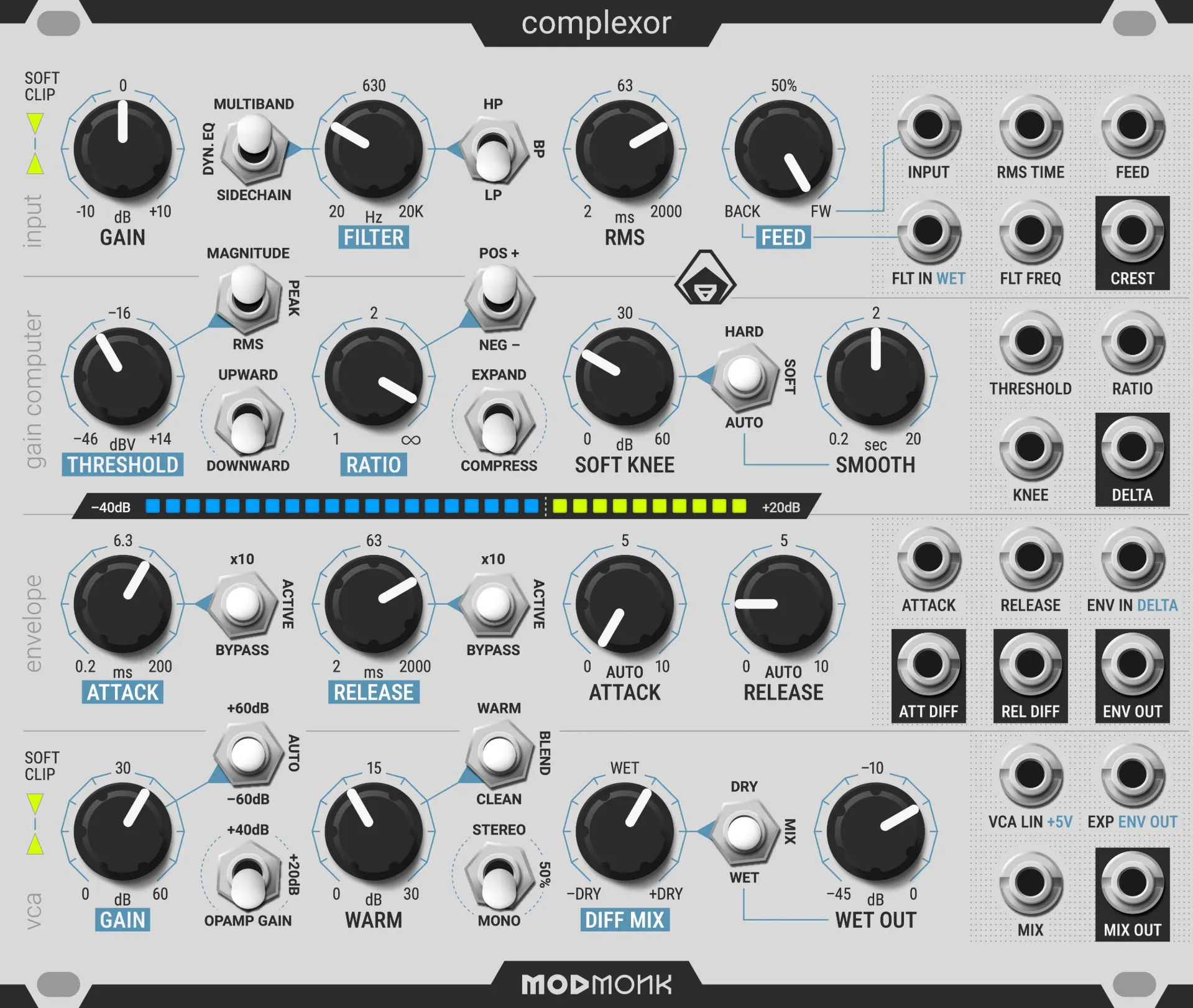
Unlike standard compressors restricted to downward compression, complexor supports upward compression, downward compression, upward expansion, and downward expansion too. These modes can be combined with adjustable compressor topologies (external sidechain, feedforward or feedback), multiple filter modes (traditional sidechain filtering, dynamic EQ or Multiband modes), 3 different pre-threshold level detection modes (Magnitude, Peak or RMS), automatic gain compensation, positive and negative ratios, and soft, auto-soft, or hard knee settings, stereo linking, saturation, unity gain matched 4 quadrant parallel compression, soft clipping, patch programmability and voltage control on almost all parameters. The result is a significantly broader array of dynamic shaping possibilities, surpassing the capabilities of traditional dynamics processors.

Program-Dependent Dynamics

The module employs automatic, program-dependent compression, dynamically adjusting attack and release times based on the input signal’s crest factor. By continually adapting to both transient and sustained components, it mitigates distortion and pumping artifacts commonly associated with fixed time constants. This adaptive approach allows a range of effects from natural and transparent dynamic control to new sound exploration. The more transient the input signal is, and the higher the Auto Release and Auto Attack amounts are set, the faster the envelopes get. A 10x time switch for the Attack and Release parameters allows for a wider range of control and doubles as a compensation method for the auto fast feature.

Auto Knee

Engaging the automatic knee function repurposes the Manual Soft Knee control into an adjustable Auto Soft Knee parameter. As the average gain reduction increases, the effective knee broadens. A dedicated potentiometer allows for fine-tuning the smoothing interval of the auto soft knee response over a range from 0.2s to 20s, providing nuanced control over transient handling and colouration.

Auto Gain Compensation

When the VCA’s Gain control is set to Auto Gain Compensation mode, the module maintains the waveform’s peak amplitude at 10 V peak-to-peak (±5V, +14dBV), as threshold and ratio parameters are adjusted. This helps maintain consistent signal intensity during dynamic manipulation without requiring excessive manual output compensation to match the perceived loudness between dry and wet signals. Auto-gain compensation is independent from the envelope. Auto compensation is only enabled for Dynamics Engine settings where it makes sense: it is switched off for negative ratios, except when in upward expansion mode. In other words, if the signal’s magnitude is predictable, it is compensated. A manual ±60dB offset adjustment option is also provided, to be able to fine-tune the VCA gain’s offset in a wide range. An extra +20dB and +40dB linear (distortion-free) opamp gain switch is also provided to help the VCA with clean gain compensation or to drive the output soft-clipper and saturator further. The soft-clipping circuit is directly connected to the VCA output’s transimpedance amplifier, allowing both the VCA and Opamp to be driven hard, without risking unpleasant hard clipping present in most analogue designs.

Parallel Compression

Provides both inverted and non-inverted dry signal paths to support parallel processing techniques, enabling transparent loudness enhancement, difference monitoring, and phase-inversion effects.

Programmable Filter Function

In Sidechain mode, the filter shapes the detector’s response without affecting the main audio path focusing the level detector’s response.

In Dynamic EQ mode, the filtered signal is routed to the VCA’s “mainchain” / audio path, creating a frequency-selective dynamic processing.

In Multiband mode, the module acts as a single band of a dual-band dynamics processor: the dry signal is replaced by the off-band signal (i.e., the difference between the filtered signal and the input), allowing complementary recombination like in a multiband compressors.

Filter function + Parallel Dynamics

In Sidechain mode, the output mix stage performs a linear crossfade between the dry and wet signals, enabling standard parallel compression. At 50% mix, both signals are attenuated by -6dB, ensuring unity gain (0dB) when summed.

In Dynamic EQ and Multiband modes, the mix changes to a linear summing behaviour. At 50% mix, the dry and wet signals are added without attenuation, producing a gain-compensated result.

In Multiband mode, the dry full-band signal is replaced by the off-band signal - the difference between the filtered band and the input - creating a complementary band split. The mixer then sums the band and off-band signals together. Because these are complementary and filtered using 6dB/oct filters, the recombination remains phase-accurate and maintains unity gain at 50% mix.

Feed Mix

The filter’s input can be blended between the original input signal and the filter input signal. By default, the filter input is internally normalled to the wet output (after gain and attenuation), enabling both feedforward and feedback compression configurations.

The filter input can also be overridden via an external patch cable to allow for external sidechain compression. The Feed mix still allows blending between External sidechain and the original signal.

When operating in Dynamic EQ or Multiband modes, the feed input becomes part of the main audio path, and thus the Feedback setting creates an audio feedback loop that introduces resonance into the filter. This allows for deeper sonic shaping and exploration. The Feed (Mix) CV input can then be used to “ping” the resonant filter - triggering bursts of resonance with gates or envelopes, similar to how traditional resonant filters are excited.

Stereo Link

Two modules can be linked via a single rear patch cable to enable stereo operation. This connection blends the control voltages (CVs) at each compressor’s VCA input.

Stereo linking is achieved through a passive CV mixer connecting each VCA's CV input.

Alternative stereo linking method

An alternative stereo linking method involves patching the opposite channel’s audio signal into the Filter Input, then using the Feed Mix control to blend between internal and external control signals. This allows audio signal based stereo-linking behaviour without the rear cable, and with an external Mid/Side or Sum/Difference matrix, it enables continuously blendable M/S compression.

You can also combine both stereo methods - rear link and filter input crossfeed - for more advanced stereo dynamics and creative control.

VCA CV Attenuation

If no stereo cable is connected at the back of the module, the Stereo switch instead acts as a CV attenuator, effectively reducing compression and expansion depth on that channel by the same ratio.


complexor circuitry & signal path

Advanced Sidechain Signal Processing

  • Feedforward/Feedback Topology: Continuously mix between compressor architectures to support both modern feedforward and classic feedback compressor designs, allowing users to replicate a wide range of compression characteristics.
  • Hybrid Magnitude Detector: Select Magnitude (Instant Peak, absolute gain), Peak (Peak with an RMS-like release trajectory) or RMS detection to influence how the Gain Computer interprets signal amplitude. Each mode caters to different program materials and aesthetic objectives.
  • Logarithmic Level Detection: Provides smooth gain changes that feel natural to the human ear.
  • Return-to-Threshold Behaviour: Ensures the release stage consistently returns to a defined threshold level, stabilizing gain trajectories and preventing abrupt transitions.
  • Independent Level Detectors: Decoupled attack and release detectors allow the attack stage to return independently to the release level. Altering the attack time yields a continuous, artifact-free gain reduction curve in accordance with advanced, smooth-response compressor design principles.

Ultra-Low Noise Design

Since dynamic range compression can raise the perceived noise floor, this module employs multiple strategies to preserve an optimal signal-to-noise ratio:

  • Low-Noise Input Buffering: Achieves noise levels similar to standard test equipment measurement thresholds.
  • Low-Value Resistors: Minimizes thermal (Johnson) noise, a primary noise source in analogue signal paths.
  • Parallel Quad VCA Configuration: Increases dynamic range and reduces the aggregate noise floor. Each VCA stage in the audio path uses four VCA channels in parallel, reducing noise while increasing headroom and fidelity.
  • 6-Layer PCB: Features dedicated, continuous ground planes positioned adjacent to each signal layer, ensuring controlled impedance and well-defined return paths. This layout minimizes EMI, crosstalk, and ground bounce, in line with modern high-performance analogue PCB design standards.

Multiple Saturation Characteristics

Multiple distinct nonlinear processing elements enable controlled harmonic enrichment:

  • Input Soft Limiting: Introduced directly at the main Input, soft limiting commences at +14 dBV allowing peaks to pass through unchanged at unity gain through a chain of 4 diodes, while pushing lower level signals up, creating an upward compression like soft-clipping effect. This unity-gain approach helps preserve original transient detail.
  • WaveShaper Mode: When the envelope is bypassed either through the switches or through patch programming, sending the magnitude to the gain computer turns the threshold, ratio and knee parameters into a precision waveshaper.
  • Warm Mode: A separate, bypassable saturation circuit with fine-tuneable overdrive. The Blend mode mixes the signals for parallel saturation independently from the output mixer, with an adjustable blend ratio potentiometer on the back-side of the module.
  • Output Soft Limiting: Introduced directly at the VCA output, soft limiting commences at +14 dBV and transitions to hard limiting at +20 dBV through a chain of 14 diodes, creating a downward compression like soft-clipping limiter effect. This allows creative manipulation of dynamic contours without having to worry about peak levels and hard clipping.

LED Indicator

30-segment analogue LED bar provides real-time visual feedback of the global delta from input to output or the gain change applied by the VCA from –40dB to +20dB. Each segment corresponds to a 2 dB range for a total of 60dB gain change indication. The LED brightness can be set using two trimmer potentiometers, accessible through the side of the module. Removing the jumper at the back of the module (or using an external switch or expander) allows changing the LED display from global delta to VCA CV.

Self-oscillation Mode

In Multiband and Dynamic EQ filter modes, when turning the feed potentiometer CCW to feedback, or by sending a 0-5V signal into the Feed CV Input the module goes into self-oscillation, which can function as a resonant filter or wave-shapeable oscillator. Without an input signal the Crest Factor Output can be fed back into the Main Audio Input. The resulting tone is shaped by the internal dynamics engine, with the Threshold, Ratio, and Knee controls defining the waveform character, and time and frequency constants like Filter Cutoff Frequency, RMS Time, Attack, and Release change the pitch and timbre of the sound.

All timing and frequency-related controls — RMS Time, Filter Frequency, Attack, and Release — respond to control voltages with a 1V/Oct scale, allowing full integration with sequencers, keyboards, and modulation sources. Ideal for experimental tones, FM-style textures, or feedback-driven drone synthesis. The 1V/Oct inputs are not fine-tuned or temperature compensated unlike a wide-range precision oscillator.

Waveshaper Mode

By feeding the magnitude signal into the gain computer input and bypassing both the attack and release envelopes, the compressor transforms into a highly versatile waveshaper. You can sculpt the waveform by adjusting the ThresholdRatio, and Knee parameters, along with the Expand/Compress switch giving you a wide range of distortion characteristics and harmonic enhancement possibilities. In this configuration, the module is effectively monitoring the short-term distortion effects introduced during fast compression, but presented in a sustained, easily interpretable form.

For additional control, the envelope circuit can be repurposed to smooth or shape external control voltages by patching the Delta output (gain computer’s output) directly into the VCA’s logarithmic CV input, bypassing the envelope section.

Voltage Control

The module provides voltage control over most parameters, facilitating seamless integration within modular ecosystems. Exponential inputs use a 1V/10dB for gain change parameters and 1V/Octave for peak detectors, slew limiters, envelope times and filter frequencies.

Ergonomic Design

  • High-Quality Potentiometers: Features long-life conductive plastic potentiometers by TT Electronics, known for their stability, low noise, and smooth feel - built to withstand years of regular use. 10x more durable than carbon potentiometers.
  • Spacious Knob Layout: Potentiometers are spaced 29 mm apart vertically, providing ample room for precise manual adjustments without accidental interference between knobs.
  • Soft-Touch Knobs: All control knobs feature a rubberized soft-touch finish - comfortable and grippy, avoiding the slippery and harsh feel of hard plastic and metal.
  • One-Way Toggle Switches: All toggle switches are strictly up/down actuated, eliminating any confusion or mechanical wear from mixed directional switches. This ensures intuitive operation and improves panel durability.
  • Separated Jack Placement: All jacks are positioned on the right side of the module, clearly isolating them from the control interface.
    Outputs are distinctly labeled for quick and easy identification, even in dim lighting or tight modular racks. 
    All jacks are placed within the same row they belong to.
  • Text-Only Labels: No icons, no guesswork - every function is clearly labeled with text. No cryptic symbols, no need to cross-reference a manual mid-session. We believe interface design should support creativity, not interrupt it. Clarity always comes first.
  • Reverse Polarity Protection: Even though the power header is keyed, mistakes can happen. This module is protected against reverse power connection - whether at the PSU, distribution board, or the module itself.
    Thanks to inline diode protection (not fuses), incorrect connections will not damage the module or trip anything - the module simply won’t power on until corrected.
    Just plug it in the right way and continue without delay - no downtime, no degraded protection, just peace of mind.
  • TVS Diodes: To ensure robust performance and protection, transient suppression diodes are installed on all jack inputs. These guard against voltage spikes that can occur when plugging in cables or making accidental contact with conductive materials (including your body), shielding the internal circuitry from sudden, harmful transients. Patch in Peace!
  • Serviceability: The module was designed with future serviceability in mind. All SMD components use generously sized solder pads, making them suitable for hand soldering. Where possible, large SOIC packages were chosen to further simplify servicing and maintenance.

Specifications

  • Power: 300mA @ ±12 V via a 10-pin IDC header (Eurorack standard).
  • Size: 30 HP, 3U Eurorack format. Width: 152mm, Height: 128.5mm, Case Depth (below the level of mounting rails sitting into the case): Power unplugged: 35mm, power plugged: 42mm, with backside trimmer knob cap: 45mm. Full module depth including front and back potentiometer knobs: 72mm
  • Front Panel Isolation: The front panel and control elements (mount, pots, switches) are electrically isolated from the 0 V analogue audio reference (jack body), ensuring compatibility with chassis-grounded Eurorack systems and maintaining safety standards.
  • CE and RoHS compliant.
  • Complete signal path diagram (High level schematics)
  • Made with love in the EU: Designed and Assembled in Italy and Hungary

As part of an ongoing refinement process, design details, features, and specifications may evolve before final production.


complexor user interface

Input

Panel Controls

  • Input Gain Pot: Fine-tune input gain from –10dB to +10dB. A Soft Clipper on the gain stage prevents hard clipping to occur allowing the input to be driven harder. Hotter input signals can be attenuated to increase internal headroom.
  • Filter Function Switch: Select between Sidechain Filtering, Dynamic EQ, or Multiband modes.
  • Filter Frequency Pot: From 20Hz to 20kHz
  • Filter Response Switch: Configurable 1 pole (6dB/oct) highpass, lowpass, or bandpass.
  • RMS Time Pot: Adjust the time constant for RMS calculation from 2ms to 2000ms. This affects both the RMS and Peak signals in the gain computer (pre-threshold smoothing), the Auto Attack / Release and the Crest Factor output.
  • Feed Mix Pot: Input mixer for the filter with a linear crossfade between feedforward (main input) and feedback (filter input). When an external cable is plugged into the filter input overriding the normalled wet output, the Feed mix allows crossfading between the original signal and an external sidechain. When using Dynamic EQ or Multiband modes the filter input jack can also be used as an auxiliary audio input.

Inputs and outputs

  • Main Audio Input: Primary audio signal input. This signal is affected by the Gain pot and forms the main audio path to the VCA, as well as the feedforward signal used in detection.
  • RMS Time CV in: Exponential 1V/O. Higher values = slower rms
  • Feed Mix CV in: Linear –5V: FeedForward / Input +5V: FeedBack / Filter Input Higher values = more feedback (The potentiometer is inverted: CCW=FB +5V, CW=FF –5V).
  • Filter Input Audio in: Auxiliary input mixed with the main input via the Feed Mix pot before entering the filter. It is normalled to the Wet Output, enabling internal feedback compression in Sidechain mode and audio feedback in Dynamic EQ and Multiband modes. When patched, it functions as an external sidechain source, allowing for duckingstereo linking, or other advanced dynamic interactions.
  • Filter Frequency CV in: Exponential 1V/O. Higher values = higher frequency
  • Crest Factor CV out: Peak with an instantaneous attack and a release envelope, divided by RMS. The time constant is adjustable using the RMS Time potentiometer. This is the same signal that is used to drive the Envelope section's Auto Attack and Auto Release, but inverted (positive polarity for usefulness in a modular environment). Logarithmic 1V/10dB curve.

Gain Computer

Panel Controls

  • Threshold Pot: from –46dBV (±5mV) to +14dBV (±5V). Sets the gain computer’s sensitivity where the dynamics engine should start to engage.
  • Gain Computer Switch: Selects the signal level detection method used before the threshold is applied.

    • Magnitude: Measures the instantaneous absolute peak level with no pre-smoothing. Attack and release smoothing can still be applied in the envelope section. This mode is ideal for aggressive, precise compression with maximum transient sensitivity or when using the module in waveshaper mode.
    • Peak: A true peak detector with instantaneous attack and an RMS-like release curve. When the Attack stage is bypassed in the envelope section, this mode can act as a brick-wall limiter, offering adjustable protection against clipping over the threshold.
    • RMS: Root Mean Square detection produces a smoother compression response by averaging the squared signal before taking the square root. This creates a rounded envelope shape that aligns more closely with human loudness perception - offering naturally softer compression with faster perceived attack and longer, more forgiving release curves. Because the signal is averaged and peaks are rounded off, slower RMS time constants cause the threshold to engage further into the knob’s range, shifting compression onset closer to the midpoint of the threshold control. The Attack and Release section smoothes the sidechain signal further, preventing discontinuities caused by the threshold level cutoff.
  • Ratio Pot: Sets the compression or expansion intensity - from 1:1 (no gain change) up to 10,000:1 (“infinity”), resulting in hard limiting at the extreme.
  • Ratio Polarity Switch: Determines how the ratio behaves in compression or expansion modes:

    • Positive
      Positive ratios apply standard compression, approaching limiting as the ratio increases.
    • Negative
      Negative ratios invert the compression curve beyond the limiting point, folding the signal back onto itself in the classic Downward Compression mode of the Dynamics Engine. This creates more extreme, pumping-style effects. It also allows the module to be used as a precision wavefolder in waveshaper mode. Negative ratios are extremely useful in the Expand mode to allow the module to go beyond conventional expander and gate effects, enabling dramatic up/down expansion for creative or sharp dynamic effects.
  • Upward/Downward Switch: Determines the Compression or Expansion direction by selecting between below-, or above-threshold values depending on the Expand/Compress switch.
  • Expand/Compress Switch: “Expand” stretches and “Compress” reduces the range of the gain change, or “delta” beyond the threshold. These 2 switches allow for 4 different Modes of Operation for the Dynamics Engine:

    • Downward Compression: Traditional compressor and limiter mode reducing dynamics for signals above the threshold level.
    • Upward Compression: Keeps the peaks unchanged and directly raises the level of lower level signals below the threshold. Since the maximum magnitude of the signal is not predictable in this mode, the Auto Gain Compensation is turned off in this mode. Use the manual setting on the VCA gain switch & pot to compensate for gain changes.
    • Downward Expansion: Classic Gate effect muting signals below the threshold. Negative ratios help achieve a stronger muting effect.
    • Upward Expansion: Expander effect increases dynamics where the values below threshold are unchanged, or uniformly attenuated with gain compensation to avoid clipping. Values above the threshold will get amplified, the louder the signal the greater the expansion.
  • Soft Knee Pot: Adjusts the curvature around the threshold from 0 to 60dB, gradually easing into compression. This results in a smoother, more natural onset of gain reduction, rather than an abrupt transition.
  • Soft Knee Switch: Selects how soft knee behaviour is applied:

    • Hard: Disables soft knee. Gain reduction begins sharply at the threshold.
    • Soft: Enables manual control of knee softness using the Soft Knee Pot.
    • Auto: Enables dynamic knee behaviour, replacing the manual soft knee pot with an automatic version that adjusts the knee depth based on the average gain reduction. The greater the sustained gain reduction, the stronger the knee effect.
  • Auto Soft Knee Smooth Pot: Sets the slew rate (time constant) for how quickly the Auto Soft Knee responds to changes in average gain reduction. Ranges from 0.2 to 20 seconds.
    For transparent, musical results, a typical value is around 10× the release time, ensuring the auto-knee reacts smoothly to overall dynamics without overresponding to short-term fluctuations.

Inputs and outputs

  • Threshold CV in: Exponential –1V/10dB. Higher values = more compression
  • Ratio CV in: Linear scaling, supporting positive and negative values. Higher values = more compression
  • Soft Knee CV in: Exponential 1V/10dB. Higher values = softer knee, less abrupt transition from non-compressed to compressed signal.
  • Delta CV out: Displays raw gain changes before the envelope, for analysis, monitoring and further CV processing. Logarithmic –1V/10dB curve. When using the Peak or RMS setting in the Gain Computer a pre-threshold smoothing is applied.

Envelope

Panel Controls

  • Attack Pot: Adjusts how quickly the compressor or expander reacts to signals exceeding the threshold. Ranges from 0.2 ms to 200 ms. Shorter times allow less transients to pass uncompressed, decreasing punch while increasing loudness, at the cost of more distortion and reduced dynamics, approaching waveshaping or clipping behaviour.
  • Attack Switch:

    • 10x: Multiplies the attack time range by 10, useful for auto-leveling or compensating for fast crest-based responses.
    • Active: Enables the attack envelope stage.
    • Bypass: Disables the attack stage. In downward compression mode with the release envelope still active, this effectively turns the module into a brick wall limiter fully catching all transient peaks. With both attack and release bypassed, and the gain computer switch is in “Magnitude” mode, the module behaves as a waveshaper.
  • Release Pot: Controls how quickly the gain returns to normal after the signal falls below the threshold. Ranges from 2 ms to 2000 ms. Faster release reduces pumping while increasing loudness, but increases distortion, especially in low-frequency content, converging toward a clipper-like response at the lowest (fastest) settings.
  • Release Switch:

    • 10x: Multiplies the release time range by 10 for gentler dynamics processing or to complement Auto Fast behaviour.
    • Active: Enables the release envelope stage.
    • Bypass: Disables the release stage. Useful for isolating the effect of release or enabling waveshaper behaviour when attack is also bypassed.
  • Auto Attack & Auto Release Pots: These control adaptive envelope behaviour based on the crest factor (ratio of peak to RMS energy). Turning them clockwise reduces the attack and release times and increases the sensitivity: the compressor reacts more quickly to transients, while preserving longer release curves for low-frequency or sustained content. This ensures fast response without introducing distortion yielding a smooth, program-dependent envelope ideal for a wide range of musical material.

Inputs and outputs

  • Envelope input CV in: Independent input of the envelope, normalled to the delta output of the gain computer.
  • Attack Time CV in: Exponential 1V/O. Higher values = slower attack
  • Release Time CV in: Exponential 1V/O. Higher values = slower release
  • Envelope output CV out: “Level Detector” output, the Smoothed Compression/Expansion Envelope.

VCA

Panel Controls

  • VCA Gain Pot: Sets the gain compensation for the VCA, with behaviour depending on the VCA Gain Switch mode.
  • VCA Gain Switch:

    • Manual: VCA Gain Pot provides manual gain adjustment across a ±60 dB range.
    • Auto: Automatically compensates output gain based on the Threshold and Ratio settings including their CV inputs. Maintains nominal output levels up to +14 dBV (10 Vpp, ±5 V) regardless of dynamics settings, ensuring consistent loudness in all operating modes. Auto gain is disabled in upward compression mode.
  • Opamp Gain Switch: Activates a linear, low-noise gain stage following the VCA, helping the VCA in high gain scenarios.
  • Warm Pot: Distortion drive controlling the amount of saturation applied to the VCA output.
  • Warm Switch: Analogue mechanical bypass:

    • Warm: Fully engages the saturator.
    • Blend: Mixes the saturated signal with the clean signal for subtle harmonic colouration while maintaining the punch and clarity of the unsaturated signal. The blend amount can be fine-tuned by the crossfader potentiometer at the back of the module.
    • Clean: Bypasses the saturator circuit entirely.
  • Stereo Switch: When two modules are linked via the rear stereo connection, this switch enables true stereo operation:

    • Full Stereo Mode: When both modules’ Stereo switches are set to Stereo, their CV signals are mixed 1:1 - each compressor responds equally to the other’s gain reduction with a 50% + 50% mix.
    • 50% Stereo Mode: When both switches are set to 50% Stereo, the crossfeed occurs at a reduced 1:2 ratio, creating a more relaxed stereo coupling where each side retains more independence with a 75% + 25% mix. When only one switch is set to blend, the effect is even more relaxed (1:3) with a 83% + 13% mix. 
    • Mono Mode: Each linked module applies CV independently to each audio channel bypassing stereo linking.
  • Stereo Switch: When unlinked (backside jack unplugged) it functions as a compression effect attenuator. This allows counterbalancing extreme ratio settings or fine-tuning dynamic character:

    • "Stereo" position: the effect is attenuated to half: 50% CV
    •  "50%" position: the effect is a blend between no attenuation and half: 75% CV
    • "Mono" position (default): no CV attenuation: 100% CV
  • Diff Mix Pot: Crossfades between dry and processed (wet) signals using a 4-quadrant interpolator. The combination of the dry and inverted wet signals are essentially ring modulated through the mix pot and CV inputs then mixed with the wet signal.
    Enables both parallel compression (dry + wet) and difference processing (inverted dry signal mixed with wet), useful for dynamic EQ and multiband applications, or just monitoring the compressor delta.
  • Diff Mix Switch: Analogue mechanical bypass:

    • Dry: Bypasses the VCA (compression/expansion), but still applies input gain and input soft clipping. In multiband mode, this allows auditioning the off-band partial of the signal going into the filter.
    • Mix: Enables full dry/wet blending as determined by the Diff Mix Pot and Mix CV input.
      Useful for parallel dynamics or recombining filtered bands in multiband/dynamic EQ modes.
    • Wet: Bypasses the mixer, outputting a 100% processed signal. Useful when parallel mixing isn’t needed, reducing the noise floor by bypassing the mixing circuitry. It can also be used to monitor the wet signal without turning the pot away from a carefully set mix blend amount.
  • Wet Output Pot: Post Fx and Pre Mixer Gain Trimmer adjustable from –45dB to 0dB this control ensures precise level adjustments after compression/expansion, soft limiting, and saturation/overdrive. This placement enables loudness matching between the processed and original signals without affecting the warm saturator circuitry, facilitating a seamless parallel processing workflow.

Inputs and outputs

  • VCA Exp CV in: Exponential voltage control of the core VCA (–1V/10dB, normalled to the level detector output, allowing inserting into and modulating the VCA’s CV signal. In “Downward” mode, Higher values Decrease gain. In “Upward” mode, Higher values Increase gain.
  • VCA Lin CV in: Linear voltage control of the core VCA, normalled to +5V, allows inserting external modulation to the VCA CV input. Higher values = louder signal. Unlike the Exponential CV Input the Linear CV input is independent of the up/down switch. Normalled to +5V.

    • 0V: –100dB = VCA muted
    • +5V: 0dB = VCA unity gain
    • +10V: +6dB = VCA 2x gain
  • Mix CV in: 3 channel Linear interpolator control enabling four quadrant parallel processing.

    • –5V: –Dry (inverted)
    • 0V: +Wet
    • +5V: +Dry (non-inverted)
  • Main Audio Output: Output stage as determined by the mix switch (Dry, Mix, or Wet)

Back Panel Adjustments

Fine tune the Warm Blend ratio using the potentiometer on the back side of the module.

Enable Stereo Link mode for consistent stereo imaging.

Two additional Audio and CV expansion headers are available at the back of the unit:

Audio Expander Outputs:

1. GND

2. VCA Dry inverted

3. Feed Mix inverted

4. GND

5. Filter Highpass

6. VCA Dry

7. Filter Bandbass

8. GND

9. Filter Lowpass

10. Warm inverted

11. Filter

12. GND

13. Filter Difference (HP>LP, BP>Notch,LP>HP)

14. Mix

15. VCA Wet

16. VCA Wet inverted

17. GND: allows parking the jumpers when an expander is not connected.

18. GND: allows parking the jumpers when an expander is not connected.

19. GND: provides a ground reference for the Warm DC Input using a jumper when an expander is not connected

Audio Expander Inputs:

20. Warm DC Input 40KΩ with 4x attenuation (30KΩ/10KΩ voltage divider to ground)

CV expander outputs:

1. Magnitude Log –33mV/dB

2. VCA CV Log –33mV/dB

3. Magnitude Linear

4. GND

5. Magnitude Squared Linear

6. VCA CV Linear 0dB = 5V, –100dB = 0V

7. Magnitude Squared Peak Linear

8. GND

9. Magnitude Squared Mean Linear

10. VCA CV Linear inverted & offset 0dB = 0V, –100dB = 5V

11. Magnitude Squared Peak Log -33mv/dB

12. Magnitude Squared Mean Log -33mv/dB

13. GND: allows parking the jumpers when an expander is not connected.

14. GND: allows parking the jumpers when an expander is not connected.

15. Threshold Log inverted 33mV/dB: used for limiting the knee using a jumper when an expander is not connected.

17. +5V reference: allows switching the LED monitoring mode to display global delta using a jumper when an expander is not connected.

19. GND

CV expander inputs:

16. Knee Limiter: connect 15. and 16. together to constrain the soft knee curve, ensuring it never exceeds the threshold. This prevents unwanted changes in peak in exchange for reducing the effect of the soft knee knob in lower threshold settings.

18. LED monitoring mode switch CV: +5V = LEDs display the raw VCA CV input, bypassing the effects of VCA output Saturation, Warm Circuitry, Opamp Gain, Wet attenuator and output Mix. 0V = display the roundtrip gain change between the input trim potentiometer and the final mix output. Connect 17. and 18. to enable the switch for monitoring the final applied Control Voltage to the VCA. Leave it unconnected for monitoring the global gain delta. Using the CV monitor helps in adjusting the VCA gain compensation to allow the VCA to operate in its 0dB sweet spot range, while global gain delta monitoring can help understand the full effect of the module (excluding the input gain potentiometer)

20. GND

Set LED brightness with the single-turn trimmer potentiometers located at the bottom side of the module. These trimmers are meant to be a set-and-forget current limiter setting to match the brightness of the two different colour LEDs, since trimmer components are not designed to withstand daily usage.


reserve you module 
today


pre-order now!


and all your synths shall be 
forgiven!