Skip to Content
ModMonk
  • 0
  • 0
  • Sign in
    • Home
    • Complexor Eurorack
    • Complexor Plugin
    • Terms
    • Contact Us
ModMonk
  • 0
  • 0
    • Home
    • Complexor Eurorack
    • Complexor Plugin
    • Terms
    • Contact Us
  • Sign in
  1. All products
  2. Eurorack
  3. complexor
  4. Eurorack
Pricelist: - Pricelist
complexor

complexor

pre-order 2026


3U 30HP Eurorack Analogue Modular Auto Compressor, Expander, Dynamic EQ, Saturator & Feedback FX Processor.

Free Worldwide Shipping for the first 70 pre-orders!

A limited run of 70 modules will be produced in the first round of production, shipping by the end of 2026. Secure your module today!

This instrument is developed through careful iteration. Design, features, and specifications may change.

100% analogue control and signal path. Your hardware purchase includes the DSP plugin version of the unit, a €149 value, at no additional cost.

Contact Us
Price
1,199.00 € 1,199.00 €
(Tax included)
Terms and Conditions
Documents
ModMonk Complexor 30HP Block Diagram.pdf ModMonk Complexor Dynamics Engine Cheat Sheet.pdf

complexor

introduction


A playable, circuit-bent, all-analogue dynamics processor and creative sound-shaping engine for Eurorack.


What it is:

Complexor combines an auto compressor, expander, gate, limiter, dynamic EQ, waveshaper and feedback machine into a single 30 HP analogue module.


Why it is good:

Complexor pairs the musical transparency of intelligent automation with the immediacy of pure analogue hardware. Attack and release dynamically adapt to incoming signal dynamics, preserving transient punch without having to compromise with excess pumping or low-frequency distortion. Every time constant and automation remains tunable and individually bypassable. Human-engineered from the ground up by ModMonk, its parallel quad VCA signal path delivers studio-grade low-noise performance with zero digital aliasing.


What it is for:

Perfect for bringing life to any sound source, gluing drums, taming wild modular signals, enhancing frequencies with dynamic EQ, or pushing sounds into warm saturation and feedback resonance.

playable analogue fx processor

A versatile analogue dynamics processor designed for modular synthesis. Combining feedforward, feedback, and sidechain topologies with real-time crest-factor parameter automation, it provides predictable, low-noise dynamic range control with comprehensive CV access.

learn more

science meets art & engineering

Rooted in established dynamic range control research, Complexor implements decoupled peak detection, adaptive attack and release time constants, and average gain-reduction knee modulation to eliminate audible artefacts like pumping and low-frequency distortion.

more details

complexor

prototype demo video


complexor

main features

Analogue Modular Auto CompressorDynamics EngineBeyond Conventional Downward CompressionProgram-Dependent DynamicsAuto KneeAuto Gain CompensationParallel CompressionProgrammable Filter FunctionFilter Function + Parallel DynamicsFeed MixStereo LinkAlternative Stereo Linking MethodVCA CV AttenuationDynamics Modes + Envelope

Analogue Modular Auto Compressor

Developed by ModMonk, Complexor is an analogue auto up/down compressor, limiter, expander, gate, saturator, filter, dynamic EQ, and waveshaper in Eurorack format. It implements established principles of program-dependent dynamic range control within a flexible, patch-programmable modular architecture. The design pairs precision low-noise analogue circuitry with voltage control over all primary parameters, offering automated, artefact-free dynamics alongside the immediate, zero-latency response of dedicated analogue hardware.

Rather than replicating a single vintage compressor topology, Complexor provides an adaptable architecture. It can reproduce the dynamic behaviour of optical, FET, and modern VCA compressors alike, with the added benefit of complete freedom from digital sampling artefacts and aliasing during heavy non-linear processing.

Dynamic range compression can be used for transparent dynamic control or for deliberate creative colouration. When subtle control is required, the automated time constants adapt continuously to the signal ballistics to prevent audible pumping or low-frequency distortion. When driven harder, deliberate gain modulation and diode soft-limiting introduce controlled harmonic enrichment, while internal feedback loops can push the filter into self-oscillation. Because all automated parameters can be manually biased or completely overridden, the user retains full artistic control over both transparent correction and intentional character.

Dynamics Engine

Beyond Conventional Downward Compression

Most audio compressors operate solely in downward compression. Complexor provides four distinct static transfer characteristics: upward compression, downward compression, upward expansion, and downward expansion. You can freely pair these modes with switchable topologies (feedforward, feedback, or external sidechain), three detection methods (Instant Magnitude, Decoupled Peak, or true RMS), automatic make-up gain compensation, negative compression ratios, flexible knee curves, diode soft-clipping, and full CV control. Whether you need to raise low-level detail without altering peaks, clamp dynamic overshoots, or gate background noise, Complexor provides the precise transfer curve required.

Program-Dependent Dynamics

Complexor features automatic, program-dependent dynamic response, adjusting attack and release time constants in real time based on the input signal's crest factor (the ratio between peak and RMS levels). Signals with high transient content automatically yield shorter time constants to catch rapid onsets and prevent drop-outs. Conversely, steady-state or low-frequency signals automatically lengthen the release time to avoid excessive gain modulation and harmonic distortion (motorboating). Both Attack and Release controls include a 10× range switch, extending the time constants for applications requiring very slow levelling or microsecond transient limiting.

Auto Knee

The automated knee mechanism adapts the transition width based on the compressor's average gain reduction. For signals with modest gain reduction, the compressor maintains a narrower, firmer knee to efficiently limit peaks. Under heavier, sustained compression, the knee width automatically broadens to provide a softer, less perceptible transition into gain reduction. A dedicated potentiometer adjusts the averaging filter time constant from 0.2 s to 20 s, allowing the user to tailor how quickly the auto-knee responds to changing dynamics.

Auto Gain Compensation

In Auto Gain mode, the sidechain computer calculates the expected gain reduction based on the current threshold and ratio settings, automatically adjusting the output level to maintain a nominal 10 V peak-to-peak (±5 V, +14 dBV) output. This allows direct A/B comparison between uncompressed and compressed signals without requiring manual make-up gain adjustment whenever the threshold is altered. An integrated diode soft-clipping network at the VCA output amplifier catches rapid overshoots, preventing harsh solid-state clipping when the circuit is driven into heavy compression.

Parallel Compression

Complexor provides both inverted and non-inverted dry signal paths via a 4-quadrant mixing stage. This supports conventional parallel compression (summing uncompressed signal with compressed signal to preserve transient punch while raising low-level detail), as well as difference processing (subtracting the dry signal from the compressed output to monitor gain reduction or generate dynamic comb-filtering).

Programmable Filter Function

In Sidechain mode, the filter shapes what the detector hears without altering the audio path, making it ideal for high-pass sidechain filtering to stop heavy kick drums from triggering compressor pumping.

In Dynamic EQ mode, the filtered signal feeds the main audio path into the VCA, creating frequency-selective compression or expansion.

In Multiband mode, Complexor acts as one band of a dual-band dynamics processor. The dry path carries the off-band signal (the difference between the filtered band and the input), allowing seamless, phase-accurate band recombination.

Filter Function + Parallel Dynamics

In Sidechain mode, the mix stage crossfades linearly between dry and wet signals. At 50% mix, both paths are attenuated by -6 dB to maintain clean unity gain (0 dB) when summed.

In Dynamic EQ and Multiband modes, the circuit switches to linear summing. At 50% mix, dry and wet signals are combined without attenuation, keeping gain fully compensated.

In Multiband mode, the dry full-band signal is replaced by the off-band signal (the input minus the filtered band). Because the split uses complementary 6 dB/oct filter slopes, the summed output remains strictly phase-coherent and preserves unity gain at 50% mix.

Feed Mix

The filter input can be blended smoothly between the original audio input and the filter input. By default, the filter input is normalled to the wet output, allowing continuous transition between modern feedforward and classic feedback compression.

Patching an external cable into the filter input overrides the normalled connection for external sidechain ducking, while the Feed Mix knob lets you blend between external ducking and internal compression.

In Dynamic EQ or Multiband modes, the filter input feeds the main audio path. Turning towards Feedback creates an audio feedback loop that sends the filter into self-resonance. You can also use the Feed Mix CV input to excite or ping the resonant filter with gates or triggers, generating percussive acoustic-like transients.

Stereo Link

Link two Complexor modules with a single rear patch cable for matched stereo operation. The link blends the control voltages (CVs) directly at each module's VCA input via a passive CV network.

When used alongside an external Mid/Side matrix, the stereo link switches let you dial in precise, blendable M/S compression.

The stereo switch settings on each module determine the CV coupling law:

Module A switch Module B switch

Module A CV

Module B to A CV

mono anything 100%

0%

50% 50% 83%

17%

50% stereo 75%

25%

stereo stereo 50%

50%

Alternative Stereo Linking Method

You can also link two channels without the rear cable by patching the opposite channel’s audio signal directly into the Filter Input, then using Feed Mix to blend between internal and external control. This gives you audio-rate sidechain cross-linking with independent sidechain filter settings for each channel.

Paired with an external Mid/Side matrix, this setup allows continuously variable M/S compression.

You can even combine both methods by linking the rear CV bus while cross-feeding audio into the filter input, opening up intricate and highly responsive stereo imaging.

VCA CV Attenuation

When no stereo link cable is connected at the rear, the Stereo switch conveniently doubles as a CV depth attenuator, scaling back the overall compression or expansion intensity on that channel.

Stereo Switch position

VCA CV attenuation

mono

0%

50%

25%

stereo

50%

Dynamics Modes + Envelope

In downward mode, the exponential VCA CV input reduces gain as voltage increases. In upward mode, the polarity flips so that positive CV boosts gain, keeping the envelope cleanly in the positive voltage domain at all times.

The Attack and Release controls always govern the internal envelope generator. Because the control voltage polarity switches between upward and downward modes, their perceptual impact on loud and quiet passages adapts accordingly:

Mode Dynamic Action Auto Gain Attack Release
Downward Compression Attenuates loud signals on How fast loud signals are attenuated How fast gain returns on quiet signals
Upward Compression Amplifies quiet signals off How fast quiet signals are amplified How fast gain returns on loud signals
Downward Expansion Attenuates quiet signals off How fast quiet signals are attenuated How fast gain returns on loud signals
Upward Expansion Amplifies loud signals on How fast loud signals are amplified How fast gain returns on quiet signals


Check out our Dynamic Engine Cheat Sheet PDF for a visual explanation.


complexor

circuitry & signal path

Advanced Sidechain Signal Processing Ultra-Low Noise Design Multiple Saturation Characteristics LED Indicator Self-Oscillation Mode Waveshaper Mode Voltage Control Ergonomic Design Specifications

Advanced Sidechain Signal Processing

  • Feedforward/Feedback Topology: Continuously blend between feedforward and feedback detector topologies. Feedforward derives the control signal directly from the input, enabling precise mathematical limiting and negative ratios. Feedback derives the control voltage from the VCA output, reducing the dynamic range presented to the detector and producing the gentle, progressive dynamic onset characteristic of classic analogue compressor circuits.
  • Hybrid Magnitude Detector: Choose between Instant Magnitude (instantaneous absolute peak), Decoupled Peak (instantaneous attack with smooth, independent release), or true RMS detection. Each mode reacts with distinct ballistics, from single-sample transient catching to psychoacoustically aligned energy integration.
  • Logarithmic Level Detection: Signal detection and gain computer operations are performed in the decibel domain. This ensures that the exponential discharge of the detector capacitor translates into a linear release rate in decibels per second, providing smooth gain recovery that matches human loudness perception.
  • Return-to-Threshold Behaviour: Decoupling the detector and referencing the envelope to the threshold level eliminates the release discontinuities and truncation artefacts that occur in return-to-zero detectors when input levels fall below the threshold.
  • Independent Level Detectors: Decoupled attack and release stages prevent the release resistor network from loading the attack circuit, ensuring that the detected peak voltage remains accurate regardless of how short the attack time constant is set.

Ultra-Low Noise Design

Compression naturally brings up the noise floor during quiet passages, so Complexor is built with multiple layers of low-noise engineering:

  • Low-Noise Input Buffering: Studio-grade input stages keep self-noise down at test-bench measurement limits.
  • Low-Value Resistors: Drastically reduces thermal (Johnson) noise right across the analogue signal path.
  • Thin-Film Resistors: Specified throughout critical audio paths to virtually eliminate 1/f excess flicker noise.
  • Parallel Quad VCA Architecture: Each VCA stage in the audio path runs four VCA channels in parallel, cutting the noise floor in half while boosting dynamic range and audio headroom.
  • 6-Layer PCB Layout: Continuous ground planes flank each signal layer, shielding audio traces against EMI, crosstalk, and power supply hum.
  • Sidechain Gain Compensation: Instead of boosting makeup gain after the VCA (which amplifies circuit hiss), Complexor calculates makeup gain directly within the sidechain computer, keeping the output noise floor pristine.

Multiple Saturation Characteristics

Four distinct analogue stages provide rich harmonic saturation and limiting:

  • Input Soft Limiting: Placed right at the main input, a four-diode ladder begins gentle soft-limiting at +14 dBV. Peaks pass through cleanly at unity gain while lower-level content is brought up, creating a natural upward-compression soft-clip that preserves transient punch.
  • Waveshaper Mode: Bypassing the envelope stages turns the Gain Computer into an analogue waveshaper. Threshold, Ratio, and Knee become waveshaping controls, generating complex harmonic overtones in real time.
  • Warm Mode: A dedicated, bypassable saturation circuit with fine-tunable overdrive. Blend mode lets you mix saturated and clean signals in parallel, independently of the main output mixer.
  • Output Soft Limiting: At the VCA output, a 14-diode ladder eases into soft limiting at +14 dBV before gently clamping towards hard limiting at +20 dBV. You can drive the output into heavy saturation without ever encountering nasty transistor clipping.

LED Indicator

A 30-segment analogue LED bar provides instant visual feedback of the gain change applied by the VCA from –40 dB to +20 dB. Each segment covers a 2 dB step across a 60 dB range. Dual side-mounted trimmers let you calibrate the display brightness to match your rack.

Self-Oscillation Mode

In Multiband and Dynamic EQ modes, turning the Feed knob towards feedback (or sending 0–5 V into the Feed CV input) pushes the internal filter into self-oscillation, turning Complexor into a resonant filter or waveshaped oscillator. Without an audio input, you can patch the Crest Factor output back into the main input to generate autonomous tones. Threshold, Ratio, and Knee shape the waveform geometry, while Filter Cutoff, RMS Time, Attack, and Release alter pitch, resonance, and timbre.

All timing and frequency parameters (RMS Time, Filter Frequency, Attack, and Release) track 1 V/Oct CV, integrating naturally with sequencers and pitch modulation sources for FM-style textures and feedback drone synthesis. The filter's 1 V/Oct tracking is fine-tuned via an accessible calibration trimmer.

Waveshaper Mode

Patching the magnitude signal into the gain computer input while bypassing attack and release envelopes transforms the dynamics core into an analogue waveshaper. Adjusting Threshold, Ratio, Knee, and the Expand/Compress switch directly alters the transfer function, generating static non-linear transfer curves, variable saturation, and analogue wavefolding.

You can also repurpose the envelope section independently to smooth and slew external control voltages by patching the Delta CV output directly into the VCA logarithmic CV input.

Voltage Control

Nearly every parameter on Complexor is voltage-controllable. Exponential CV inputs track at 1 V/20 dB for gain parameters, and 1 V/Octave for filter frequency, envelope time constants, peak detectors, and slew limiters.

Ergonomic Design

  • High-Quality Potentiometers: Fitted with long-life conductive plastic potentiometers by TT Electronics, chosen for their smooth mechanical feel, low noise, and exceptional longevity (over 10× the lifespan of standard carbon pots).
  • Spacious Knob Spacing: Pots are spaced 29 mm apart vertically, giving your fingers plenty of room for precise adjustments during live performance without knocking adjacent controls.
  • Soft-Touch Knobs: Every pot is capped with a rubberised soft-touch knob for positive grip and tactile comfort.
  • One-Way Toggle Switches: All switches actuate exclusively up/down, keeping panel gestures intuitive and consistent while eliminating directional wear.
  • Separated Jack Field: All patch points are arranged down the right side of the panel, keeping patch cables clear of the knobs. Outputs are distinctly labelled in high-contrast text, aligned neatly with their corresponding functional rows.
  • Text-Only Labels: No cryptic iconography or confusing symbols. Every control and jack is clearly labelled with legible text, so you never need to interrupt your creative flow to check the manual.
  • Reverse Polarity Protection: Mistakes happen. Complexor features inline diode protection (not sacrificial fuses) against reverse power connections at the busboard. If connected backwards, the module simply remains unpowered until corrected, with no blown fuses, no damaged parts, and no downtime.
  • TVS Diodes: Every jack input is protected by transient voltage suppression (TVS) diodes, shielding sensitive analogue circuits against static discharges and hot-patching spikes. Patch with complete peace of mind.
  • Serviceability: Built to last and designed for future servicing. Surface-mount parts use generous solder pads and accessible SOIC packages wherever possible, ensuring straightforward maintenance and hand-soldering repairs.

Specifications

  • Power: 300 mA @ ±12 V via standard 10-pin Eurorack IDC ribbon header. Power supply not included; designed for installation into a standard Eurorack case.
  • Size: 30 HP, 3U Eurorack format. Width: 152 mm, Height: 128.5 mm. Mounting depth into case: 35 mm (unplugged), 42 mm (with power cable connected).
  • Front Panel Ground Isolation: The front panel and mounting hardware are electrically isolated from the 0 V analogue audio reference (jack sleeves), preventing ground loops in chassis-grounded Eurorack systems.
  • CE and RoHS compliant.
  • Complete signal path diagram (high-level schematics).
  • Made with love in the EU: Designed and assembled in Italy and Hungary.

As part of an ongoing refinement process, design details, features, and specifications may evolve before final production.


complexor

user interface

InputPanel ControlsInputs and OutputsGain ComputerPanel ControlsInputs and OutputsEnvelopePanel ControlsInputs and OutputsVCAPanel ControlsInputs and OutputsBack Panel AdjustmentsTrimmer Potentiometer Adjustments

Input

Panel Controls

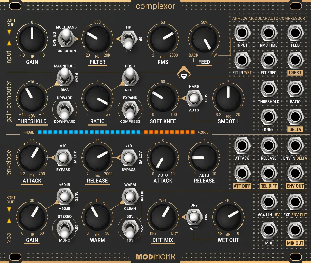
  • Input Gain Pot: Sets input level from –10 dB to +10 dB. An integrated soft-clipper catches hot transients to prevent harsh clipping, letting you drive the input hotter without unpleasant distortion or attenuate loud modular signals to preserve headroom.
  • Filter Function Switch: Selects between Sidechain Filtering, Dynamic EQ, or Multiband modes.
  • Filter Frequency Pot: Sweeps the filter cutoff from 20 Hz to 20 kHz.
  • Filter Response Switch: Selects 1-pole (6 dB/oct) highpass, lowpass, or bandpass filter characteristics.
  • RMS Time Pot: Sets the RMS detection integration window from 2 ms to 2,000 ms. This affects RMS and Peak smoothing in the Gain Computer, the Auto Attack / Release engine, and the Crest Factor CV output.
  • Feed Mix Pot: Linear crossfader between feedforward (main audio input) and feedback (filter input). When a patch cable is inserted into the Filter Input jack (overriding the normalled wet output), Feed Mix blends smoothly between the dry input and an external sidechain source. In Dynamic EQ and Multiband modes, the filter input can also serve as an auxiliary audio input.

Inputs and Outputs

  • Main Audio Input: Primary audio signal input. Formatted for modular levels, routed through the input gain stage to both the VCA and the sidechain detector.
  • RMS Time CV in: Exponential 1 V/Oct response. Higher voltage = slower RMS averaging.
  • Feed Mix CV in: Linear control (–5 V: Feedforward / Input; +5 V: Feedback / Filter Input). Higher voltage increases feedback (inverted relative to the panel knob: CCW = FB +5 V, CW = FF –5 V).
  • Filter Input Audio in: Auxiliary input blended with the main signal via Feed Mix before the filter. Normalled to the Wet Output for internal feedback compression (Sidechain mode) or audio feedback resonance (Dynamic EQ / Multiband modes). Patching here overrides the normal to accept external ducking or sidechain signals.
  • Filter Frequency CV in: Exponential 1 V/Oct tracking. Higher voltage = higher frequency. Fine-tunable via a side-mounted calibration trimmer (100 kΩ input impedance).
  • Crest Factor CV out: Peak level divided by RMS (with instantaneous attack and release curve). Logarithmic 1 V/20 dB output (positive polarity for modular utility). Useful for modulating other modules in sync with audio dynamics.

Gain Computer

Panel Controls

  • Threshold Pot: Sets the engagement threshold from –46 dBV (±5 mV) to +14 dBV (±5 V).
  • Gain Computer Switch: Chooses the pre-threshold level detection method:

    • Magnitude: Measures instantaneous absolute peak level with zero pre-smoothing filter lag. Delivers maximum transient sensitivity, and enables direct transfer-curve waveshaping when envelopes are bypassed.
    • Peak: A decoupled peak detector featuring instantaneous attack and a smooth release trajectory. Bypassing the envelope attack stage provides brickwall limiting without overshoot.
    • RMS: Computes the root-mean-square energy of the input signal via a 1-pole exponential moving average filter, closely modelling human loudness perception. Slower RMS integration time constants provide smooth levelling suited to sustained signals, shifting compression onset higher up the threshold scale.
  • Ratio Pot: Sets dynamic slope from 1:1 (unity, no gain change) up to 10,000:1 (“infinity”), approaching brickwall limiting at maximum.
  • Ratio Polarity Switch: Flips ratio response:

    • Positive: Standard compression or expansion slope, progressing towards hard limiting as ratio increases.
    • Negative: Inverts the static compression curve beyond the threshold, attenuating higher-amplitude peaks more aggressively than lower levels. In downward compression, this produces deliberate dynamic pumping; in waveshaper mode, it acts as an analogue wavefolder; in expander mode, it provides aggressive gating.
  • Upward/Downward Switch: Sets whether dynamic processing targets audio above or below the threshold, in coordination with the Expand/Compress switch.
  • Expand/Compress Switch: Selects whether signals beyond the threshold are squashed or expanded. Together, these switches provide four core dynamic modes:

    • Downward Compression: Standard compressor and limiter action, reducing dynamic range on loud passages above the threshold.
    • Upward Compression: Leaves peaks intact while boosting quiet signals below the threshold. Because peak levels depend entirely on program material, Auto Gain Compensation is disengaged in this mode; use the manual VCA Gain knob to level-match wet and dry signals.
    • Downward Expansion: Classic noise-gate and downward expansion, quieting signals that drop below the threshold. Negative ratios deliver sharp, total muting.
    • Upward Expansion: Expands dynamic range by amplifying signals above the threshold, giving greater boost to louder inputs, while leaving sub-threshold content untouched (or gently padded under auto-gain to prevent clipping).
  • Soft Knee Pot: Adjusts threshold curve softness from 0 to 60 dB, easing into gain reduction for a transparent, musical onset.
  • Soft Knee Switch:

    • Hard: Disables knee curvature; gain reduction starts abruptly at the threshold.
    • Soft: Enables manual knee width adjustment via the Soft Knee pot.
    • Auto: Dynamically scales knee width in proportion to average gain reduction, so the deeper the compression, the wider and softer the knee becomes.
  • Auto Soft Knee Smooth Pot: Sets the time constant (0.2 s to 20 s) for Auto Knee tracking. Setting this to roughly 10× your release time yields smooth, transparent knee transitions without erratic flutter.

Inputs and Outputs

  • Threshold CV in: Exponential –1 V/20 dB. Higher voltage = deeper compression.
  • Ratio CV in: Linear scaling supporting positive and negative voltages. Higher voltage = higher ratio.
  • Soft Knee CV in: Exponential 1 V/20 dB. Higher voltage = broader, softer knee transition.
  • Delta CV out: Outputs the raw gain-reduction control voltage before envelope filtering. Logarithmic –1 V/20 dB response, ideal for external modulation and CV monitoring.

Envelope

Panel Controls

  • Attack Pot: Controls how quickly gain reduction engages when audio crosses the threshold (0.2 ms to 200 ms). Ultra-fast settings catch transients cleanly; slower settings allow transient attack punch through before compression clamps down.
  • Attack Switch:

    • 10x: Multiplies attack time by 10 (up to 2 s) for gentle, slow-moving levelling.
    • Active: Normal envelope attack operation.
    • Bypass: Bypasses the attack envelope stage. With release active, downward compression becomes a true brickwall limiter. With both attack and release bypassed and Gain Computer set to Magnitude, Complexor operates as an analogue waveshaper.
  • Release Pot: Controls recovery speed once the signal drops below threshold (2 ms to 2,000 ms). Faster release boosts sustained loudness; slower release provides transparent, unhurried recovery without bass distortion.
  • Release Switch:

    • 10x: Multiplies release time by 10 (up to 20 s) for slow, wide-range program levelling.
    • Active: Normal envelope release operation.
    • Bypass: Disables release decay, freezing instantaneous gain values or enabling waveshaping when attack is also bypassed.
  • Auto Attack & Auto Release Pots: Clockwise rotation increases the scaling sensitivity to the measured short-term crest factor. High-crest transients automatically decrease the effective attack and release times to control onsets, while steady-state signals maintain longer time constants to avoid low-frequency harmonic distortion and pumping.

Inputs and Outputs

  • Attack Time CV in: Exponential 1 V/Oct. Higher voltage = slower attack.
  • Release Time CV in: Exponential 1 V/Oct. Higher voltage = slower release.
  • Envelope Input CV in: External CV input to the envelope generator, normalled to the Delta CV output of the Gain Computer.
  • Attack Diff CV out: Differential output between envelope input and attack stage.
  • Release Diff CV out: Differential output between release stage and envelope input.
  • Envelope Output CV out: Smoothed dynamic envelope CV driving the VCA core.

VCA

Panel Controls

  • VCA Gain Pot: Sets output gain compensation, governed by the VCA Gain Switch mode.
  • VCA Gain Switch:

    • Manual: Provides manual gain offset across a wide ±60 dB range.
    • Auto: Automatically compensates output gain according to Threshold and Ratio settings (including external CV). Holds peak output level steady at +14 dBV (10 Vpp, ±5 V) across compression settings.
  • Stereo Switch: When two modules are linked via the rear link cable:

    • Full Stereo Mode: Both modules set to Stereo mix their CV control voltages 1:1 (50% + 50%) for locked stereo imaging.
    • 50% Stereo Mode: Both modules set to 50% link at a relaxed 75% + 25% mix, giving each channel slightly independent dynamic movement. Setting one module to 50% and the other to Mono yields an 83% + 17% coupling.
    • Mono Mode: Bypasses stereo link; each module responds strictly to its own detector.
  • Stereo Switch (Unlinked): When no rear cable is connected, the switch functions as a handy CV depth attenuator:

    • Stereo position: Cuts CV effect depth in half (50% CV).
    • 50% position: Blends between full and half depth (75% CV).
    • Mono position (default): Full effect depth (100% CV).
  • Warm Pot: Controls drive and saturation depth into the dedicated warm distortion circuit.

  • Warm Switch: Analogue bypass for the saturation circuit:

    • Warm: Fully engages the saturation stage.
    • Blend: Mixes saturated and dry audio in parallel for subtle warmth while retaining clean transient clarity. Blend balance is calibrated via the rear trimpot.
    • Clean: Completely bypasses the saturation circuit.
  • Warm Blend Switch: Selects preset blend ratios:

    • 50%: 50% saturated, 50% clean.
    • 25%: 25% saturated, 75% clean.
    • 10%: 10% saturated, 90% clean.
  • Diff Mix Pot: 4-quadrant crossfader between dry, inverted dry, and wet signals. Supports classic parallel compression (dry + wet) as well as difference monitoring (inverted dry + wet) to isolate the compressor's gain reduction or create phase-comb effects.
  • Diff Mix Switch:

    • Dry: Bypasses the VCA dynamics path while retaining input gain and input soft-clipping. In Multiband mode, lets you monitor the off-band filter signal.
    • Mix: Enables wet/dry blending via the Diff Mix pot and Mix CV input.
    • Wet: Routes 100% processed audio directly to the output, bypassing mixing circuitry for the lowest possible noise floor.
  • Wet Output Pot: Post-FX / pre-mixer gain trimmer (–45 dB to 0 dB). Allows precise level matching of the processed signal before it enters the mix stage without altering drive into the Warm saturator, making parallel processing fast and effortless.

Inputs and Outputs

  • VCA Exp CV in: Exponential voltage control (–1 V/20 dB) normalled to the envelope detector output. In Downward mode, higher CV decreases gain; in Upward mode, higher CV increases gain.
  • VCA Lin CV in: Linear voltage control of the core VCA, normalled to +5 V. Higher voltage = louder signal. Unlike the exponential CV input, linear CV is independent of the Up/Down switch:

    • 0 V: –100 dB (VCA muted)
    • +5 V: 0 dB (unity gain)
    • +10 V: +6 dB (2× voltage gain)
  • Mix CV in: Linear interpolator CV for 4-quadrant parallel mixing:

    • –5 V: Inverted Dry (–Dry)
    • 0 V: 100% Processed (+Wet)
    • +5 V: Non-inverted Dry (+Dry)
  • Main Audio Output: Final output signal selected by the Diff Mix switch (Dry, Mix, or Wet).

Back Panel Adjustments

Stereo Link bidirectional jack connects two Complexor modules via a single cable for matched stereo imaging.

Two Audio and CV expansion headers are accessible on the rear PCB:

Audio Expander Outputs:

1. GND
2. Compressor Wet Output
3. Feed Mix Output inverted
4. GND
5. Filter Highpass Output
6. Compressor Dry Output
7. Filter Bandpass Output
8. GND
9. Filter Lowpass Output
10. Warm Output inverted
11. Filter Output inverted
12. GND
13. Filter Difference Output = Feed Mix Output – Filter Output
14. Compressor Mix Output (pre-switch)
15. GND
16. +3V Reference
17. +5V Reference
19. GND
20. +2V Reference

Audio Expander Inputs:

18. Warm DC Input (40 kΩ input impedance with 4× attenuation via 30 kΩ/10 kΩ divider to ground). Use a jumper to 2 V, 3 V, or 5 V reference for a constant DC bias offset.

CV Expander Outputs:

1. Magnitude Log Output @ –33mV/dB
2. GND
3. Magnitude Linear Output
4. Magnitude Squared Linear Output
5. GND
6. Magnitude Squared Peak Linear Output
7. Magnitude Squared Mean Linear Output
8. GND
9. Magnitude Squared Peak Log Output @ –33mv/dB
10. Magnitude Squared Mean Log Output @ –33mv/dB
11. GND
13. Envelope Release CV Output @ 33mV/dB
15. Envelope Attack CV Output @ 33mV/dB
17. Threshold Log Output @ –33mV/dB: connect to pin 18 with a jumper to limit knee curvature at low thresholds.
19. Compressor CV Log Output @ –33mV/dB

CV Expander Inputs:

12. Filter Frequency CV Input: 1V/Oct (100 kΩ input impedance), fine-tuned via side calibration trimmer.
14. Envelope Release Time CV Input @ 33mV/dB (100 kΩ input impedance).
16. Envelope Attack Time CV Input @ 33mV/dB (100 kΩ input impedance).
18. Knee Limiter Input: jumper to pin 17 to prevent soft-knee curvature from exceeding the threshold.
20. LED Display Input @ –33mV/dB (1 LED segment = 2 dB). Factory-normalled to pin 19 (Compressor CV Log Output).

Trimmer Potentiometer Adjustments

Calibrate LED display brightness using the two side-mounted trimmer potentiometers. These set the constant-current source to match the visual brightness of the two LED colours used for amplification and attenuation monitoring.

Calibrate Filter Cutoff 1V/Oct CV tracking using the dedicated side-mounted trimmer potentiometer.

These trimmers are set-and-forget calibration controls, not designed for frequent front-panel adjustment.

Reserve your module

today

and all your synths shall be

forgiven!


pre-order now!

  • Info
  • Complexor
  • Terms
  • Contact us

Social
Follow us on our social sites

Follow us
ModMonk D.D.

David Debreczeni
Via di Romagna 37/1

Trieste 34134, Italy
VAT: IT01416850327


Copyright © 2026 - Debreczeni Dávid - MODMONK D.D.